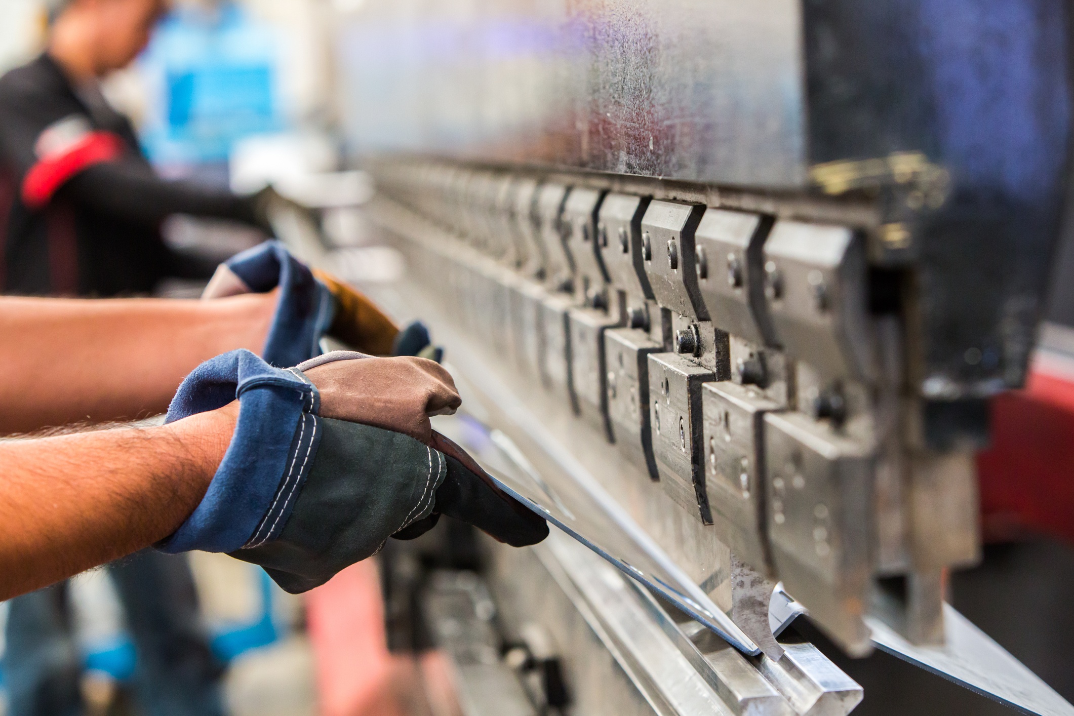
From architectural brackets to stairs, many products require precision formed angles. Bending metal into a straight-line angle is the most common form of press brake work. A top die, or punch, pushes the metal into a lower vee die to form the angle desired.
Sheet metal has characteristics that affect forming. A few characteristics that may not be familiar to those outside the fabrication shop are length of tooling, tonnage, and radius.
Length of Tooling
The overall design is limited by the maximum length of the tooling and brake frame. Depending on the material and thickness, our maximum bend length at Naimor, Inc. is 12’.
Consider Tonnage
Press brakes are rated for a maximum bending pressure, or tonnage. Longer flange length and greater thickness call for increased tonnage. Increasing the bend radius with a wider V die helps to reduce the tonnage needed to complete the bend.

Bends that run perpendicular to the material’s natural grain require slightly more pressure than those running parallel to the grain. The raw stock tends to crack and fatigue parallel to the grain, just as a sheet of wood would.
A press brake tonnage table is very useful to figure out the force needed per linear foot to bend different thicknesses of metal – Naimor can obtain up to 230 tons.
Specify a Common Radius
Sheet metal has memory and must be over-bent to achieve the desired bend angle. Overbending each flange is necessary to allow it to spring back to the correct unrestrained angle.
The amount of spring back depends on the type of metal, the thickness, grain direction and hardness. Normal spring back for mild steel is 2-4 degrees. Assigning features and placing bends for one material may be grossly inappropriate for a different material.
Sheet metal also stretches when it bends. It can crack instead of stretch, depending upon several variables, including the material used, tooling applied and the direction of the grain. As the bend radius gets smaller, the strain on the part increases. When the materials fatigue point is exceeded, cracks form.
Aluminum generally requires a larger bend radius than cold rolled steel, however this is dependent on the grade of aluminum. For example, 6061-T6 is very difficult to bend and requires an inside radius of at least 6X the material thickness, whereas 5052-T32 bends in the same way as mild steel. A good rule of thumb for steel and stainless is to keep the inside bend radius 1X material thickness.
Set Realistic Tolerances
Variation exists within the raw material. As well, each piece of equipment contributes variation during the metal forming process.
Flat parts cut with lasers are usually consistent within ±0.005 in. Press brakes typically repeat within ±0.010 in. for each bend in the part. Angle variation is usually specified at ±1 degree.
Slight indentations on polished stainless, or aluminum can sometimes occur on the outside (die side) of the part from contact with the top edges of the die. These are inherent in the metal forming process. At Naimor, Inc., we use die film to minimize these marks.
Determine Flange Width
The minimum flange width should be at least four times the stock thickness, plus the bend radius. Requiring too narrow a flange can overload the equipment, distort the part, and damage the tooling.
When multiple bends are on the same plane try and design the part so the bends all face the same direction. This will prevent the need for the operator to flip the part.
Locate Features
Features such as holes, slots, and certain notches should not be located closer than 3X material thickness plus the bend radius from the bend. Bending distorts these features and can cause a variety of problems.
Put Our Capabilities to Work
Specialized tooling to form architectural parts can be very expensive. When developing your part, it may call for a bend that requires non-standard tooling. Our experts here at Naimor, Inc. can let you know the tools that are available, or if the design should be reevaluated. Design for manufacturability requires planning for tooling access.


